Multiple-component visualization.
Revolute joint 1.
Object Tracking Robotic Arm
A robotic arm that can detect objects and perform autonomous tracking through space. The arm is built with custom metal and 3d printed parts, and runs on custom firmware and software.
Update: this project was selected as the hardware showcase winner in my EECS C106A (Robotics I) course!
Introduction
I’ve been trying to work on some challenging projects to work on to grow my skills in some specific subareas in robotics, and for the last 9 months I’ve been working on this project. The main practical goal of this project is to create a robotic arm capable of object recognition and tracking.
A secondary goal is to design a modular, well-built system that supports the possibility of future work, in regards to both hardware and software.
The necessary hardware needed to support this is just 2 revolute DOF, because it allows access to a 2d surface in a 3d space (in fact, exactly what a camera does).
The motivation and interest behind the project is less so the specific algorithm that the arm can run, but more about developing a system that can scale to become much more complex over time. Software algorithms can be swapped out fairly easily, but a good system needs a strong foundational design to support this modularity. In the ideology of Berkeley's CS 61C course and Patterson and Hennessey's RISC architecture design: keep the hardware simple, and make the software complex.
To support complex software, the system needs to have a well-defined flow of information (the specific decision-making algorithm can be swapped out or tuned). Traditionally, ROS supports this need, and accordingly, the main logic flow of this system is built in ROS.
Another real-world benefit of this project is the physical creation of a fully functional, well-built arm that supports complex software capabilities. Robotic arms are usually quite rare and very expensive to come by at the current time of writing, but the nature of the design of this arm allowed me to create it completely in my own workshop, at a fraction of the price industrial arms cost. I'm planning to use this arm in many future builds.
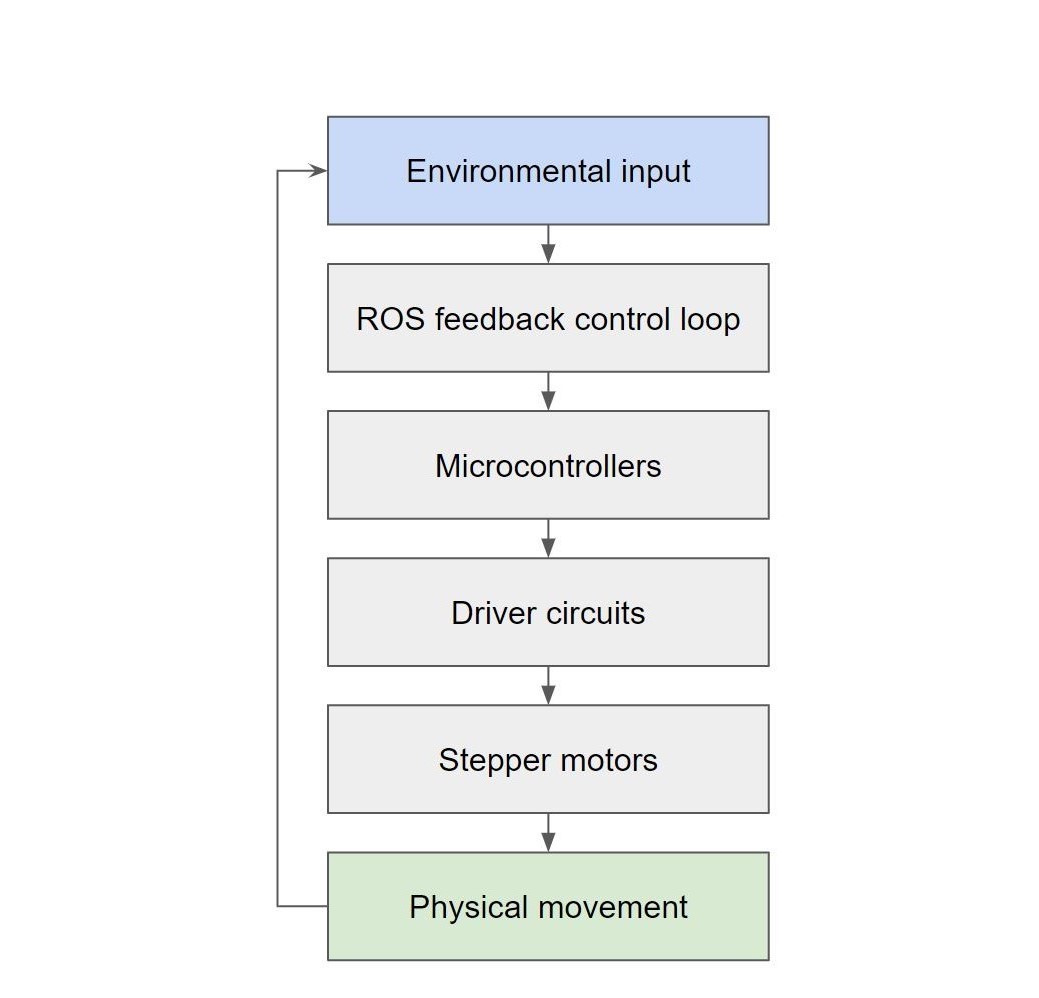
System diagram.
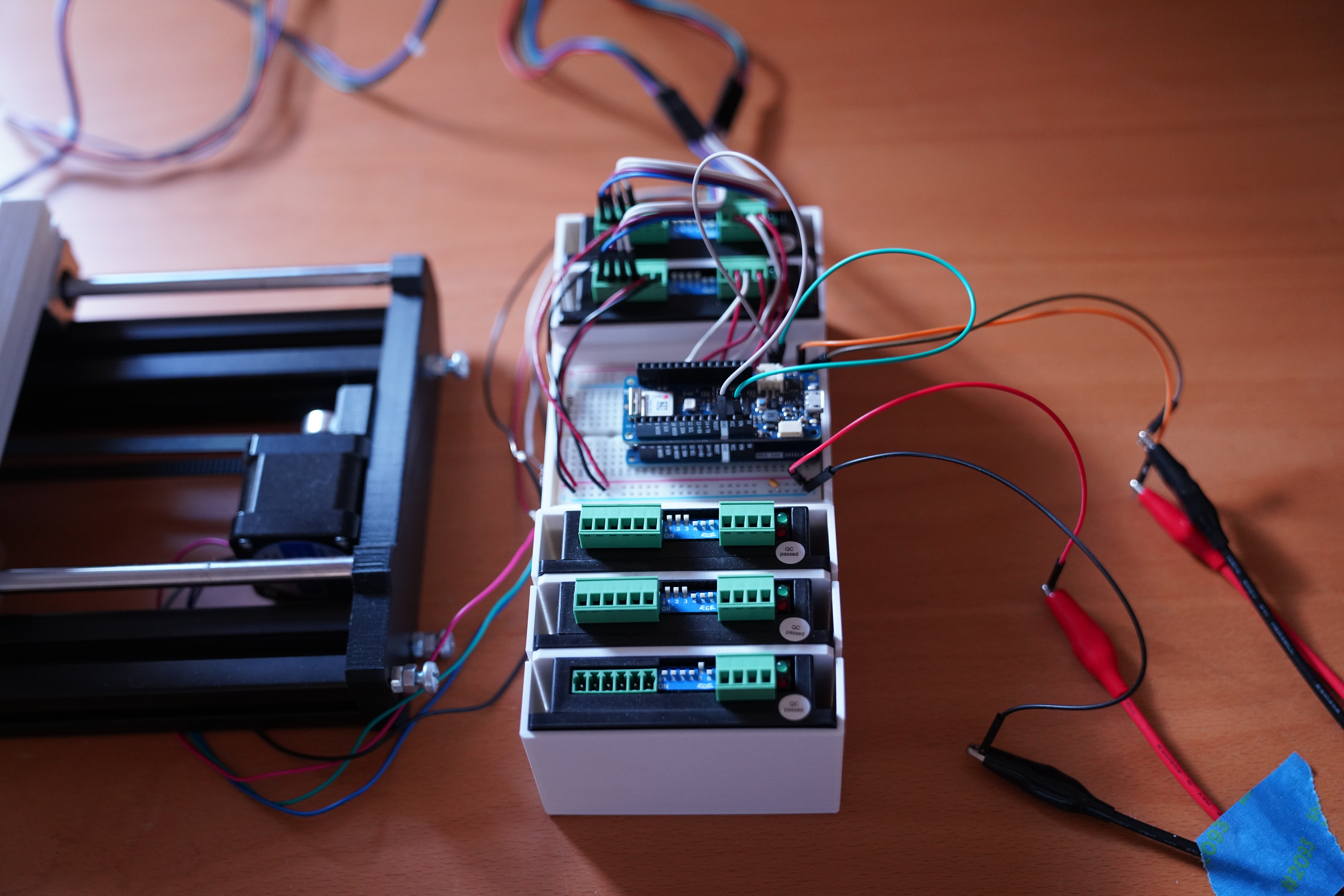
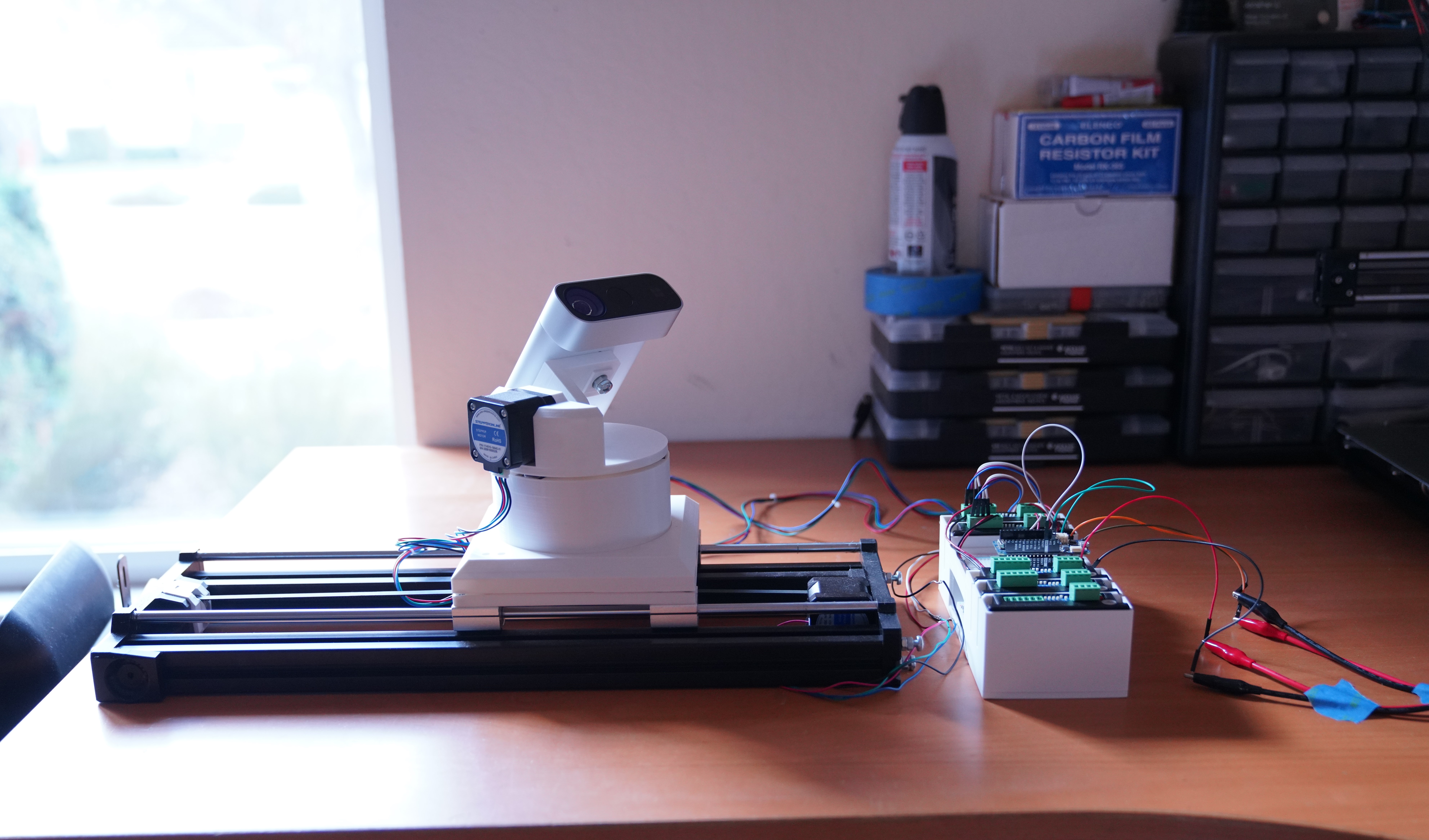
Electronics.
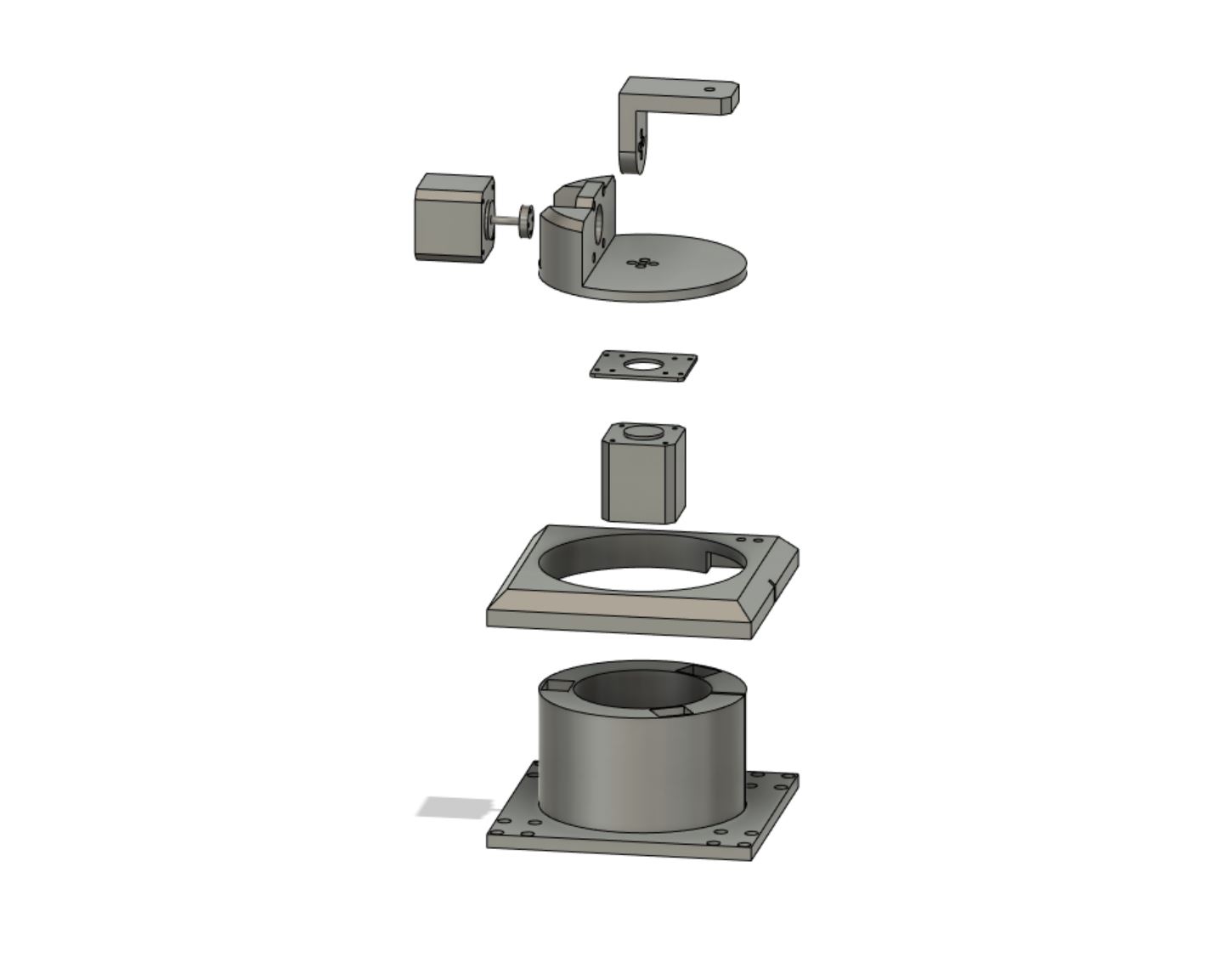
Exploded view of components.
Design
The arm currently has 3 degrees of freedom (DOF), one prismatic and two revolute. It is actuated by NEMA-17 stepper motors (favored for their smooth motion, generally good torque, ability to hold a rigid position under duress, ability to rotate 360+ degrees (unlike most high-torque servomotors), and exact position determination without encoders) and driven by DSP driver circuits.
The arm is powered by a Siglent power supply running out 24V/3A for motor actuation and 5V for a logic line. The power lines are buffered with capacitors to withstand power fluctuations.
On a low level, the arm is controlled by a microcontroller loaded with custom firmware that allows the arm to accept position and velocity inputs.
On a high level, the arm is controlled by a ROS system that acts as a control feedback loop. The arm senses the world through a Kinect sensor, which returns RGB (2d surfaces in 3d space) and depth sensor (3d points in 3d space) data. Based on its perception of the environment, it autonomously generates an appropriate response in reaction.
The physical components of the arm are 3d printed from custom models made in Fusion 360 and printed on a Prusa Mini I assembled. The base is made out of 80/20 T-slot aluminum extrusion cut down to milimeter precision, and its design is drawn from the gantry-like operation of the Prusa Mini's y-axis.
Design Ideologies
The arm is designed to be bottom-heavy in order to improve the efficiency of the revolute joints. Since each successive joint of the arm must carry the full weight of all of its successor joints, the weight becomes additive with every extra joint. To counteract this, arm designs will generally try to keep all the heavy components (motors, sensors, etc) as low as possible and translate forces upwards using timing belts or other similar means instead.
Making the first joint of the arm a prismatic joint built into the base was a design choice influenced by this idea, since the successive revolute joints avoid bearing the expensive weight of an prismatic component up top. The tradeoff is that the reachable workspace of the arm is modified--it becomes an oblong, narrow ellipsoid, in contrast with a wider but radially symmetric sphere.
All the electronics are offboard because of the same reason. There is little tradeoff to keeping the electronics and the mechanical, moving components of the arm separate, since the arm is instrinsically a static object itself (compared to, for example, an autonomous vehicle, which needs to keep all of its electronics onboard at all times). However, the weight reduction from doing this is very beneficial.
Symmetry is also an important design choice for multiple factors. The first factor is even weight distribution, which is physically important for efficient motion and extending the lifetime of the arm. Antisymmetry causes forces in undesired directions to be applied, which is not modeled for in the motor motions (and you only get a fraction of the torque--the component that lies in the direction of your motor only).
The second factor is in the calculation of forward and inverse kinematics for motion planning with the arm. Including intersecting axes makes the derivation much simpler, because it allows the choosing of a common point on multiple axes at once to cancel things out.
Careful design from the beginning can save quite a bit of time and headaches later on.
Vision: feature detection.
Vision: generalized feature estimation.
ROS system design.
Implementations
The software implementations for this project are written in Python 3 and run on a Ubuntu 18 environment. The software draws on the OpenCV and ROS Melodic external libraries and is otherwise self-written. The firmware is written as .ino files and is self-written.
Computer Vision
The vision algorithms used by the arm are built on OpenCV. The arm analyzes RGB video output to detect faces based on Haar features in an OpenCV cascade classifier, trained on an OpenCV dataset. To do this, the vision algorithm analyzes the video output frame-by-frame, essentially generating a sequence of images. Each image is converted to grayscale first (to make the classification easier computationally), and then passed into the cascade classifier.
The algorithm looks for two features: faces viewed from the front, and faces viewed from the side. From some basic tracking tests, these two features consistently outperformed the other trained features provided by the dataset. Using faces as the point of interest of the algorithm also has the playful side effect of giving the impression that the arm is directly looking at a person, which makes it much more lifelike.
The classifier can be tuned to output more correct results by training several parameters, including scaling factor, minimum neighbor count, and minimum size parameters. Each factor affects the number of false positives and false negatives classified by the model, and depends on the specific conditions of the arm environment and camera (such as lighting, facial structure, object distance, etc).
To track multiple features and multiple faces at a time, all the detected features in the frame are computed in a single general midpoint by taking the average of the lateral and vertical positions of each feature. Because the absolute midpoint of the frame is known, a difference in position can be trivially computed. This becomes the desired area of focus for our arm, and the information is sent over to a ROS planning node.
Feature detection, generalized-midpoint video examples.
ROS
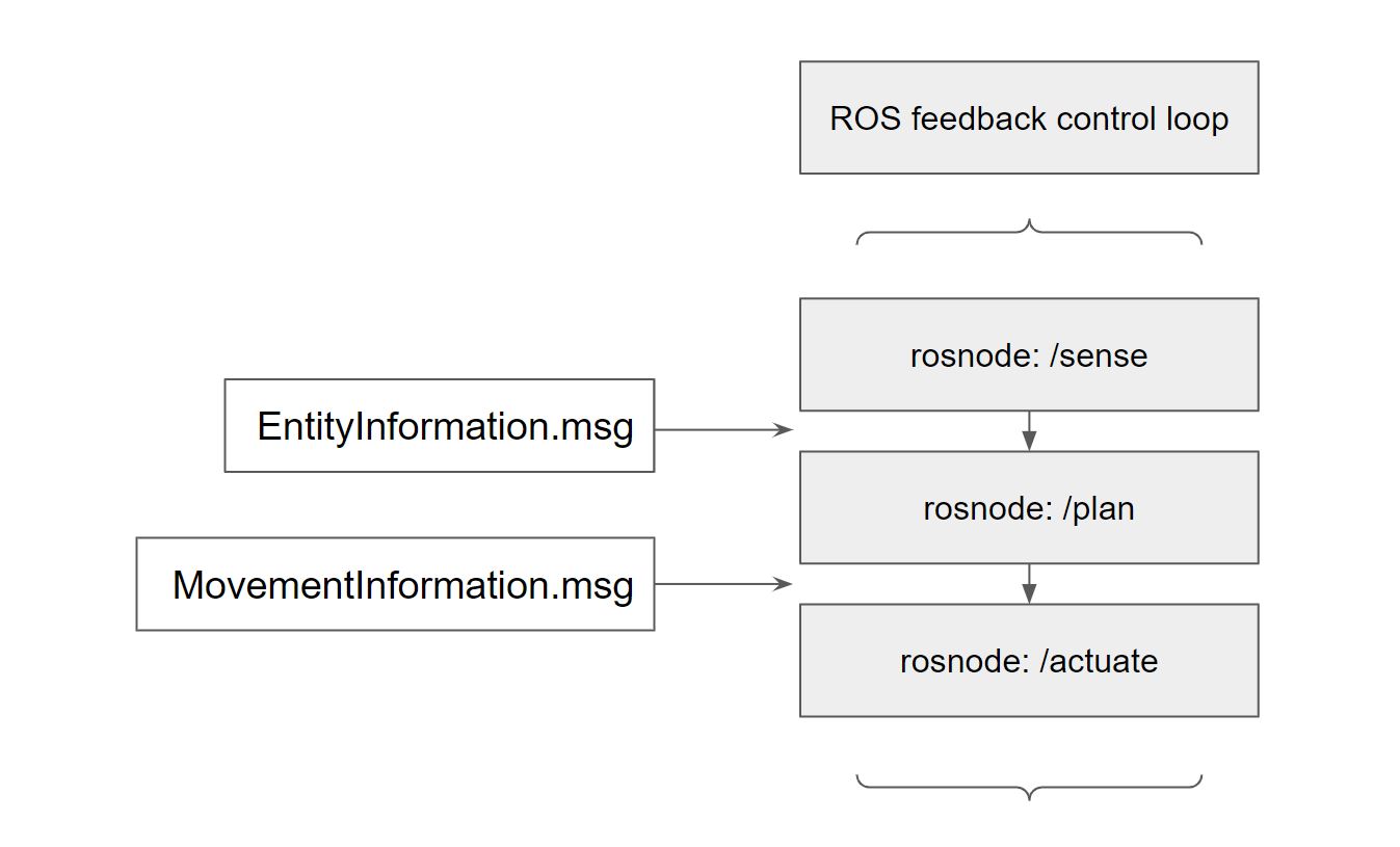
A ROS sensing node uses the Haar feature-based cascade classifier described above to detect interesting objects from image data and relays the information to a ROS planning node. In the ROS graph, this node is called /sense. It publishes a custom ROS message called EntityInformation.msg, which contains a desired point of focus and a current point of focus. This is published on the rostopic /entities.
The ROS planning node takes in the coordinates of the interesting objects, attempts to keep all of them in frame, and generates a motion plan for each axis on the arm to follow, which is sent over to a ROS actuating node. The name of this node on the ROS graph is /plan, and it subscribes to the topic /entities to receive the information it needs (through an EntityMessage). This node is also a publisher, and publishes the motion plan on the rostopic /movements through a custom ROS message called MovementInformation.msg. MovementInformation.msg contains a list of instructions that are dependent on the control stategy the node uses (for example, I implemented control strategies of both position and velocity for the arm). The following Path Planning section covers the mathematical implementation of this node in more detail.
The ROS actuating node translates the motion plan for each axis into firmware-understandable motor commands at a tuned rate of update. This frequency of update becomes quite significant later on in the performance of the arm, which is discussed in the following Results section. The name of this node on the ROS graph is called /actuate, and it subscribes to the rostopic /movements for a motion plan that it translates into firmware-understandable commands. This node also handles all of the serial line communications that interface with the microcontrollers.
Path Planning
The goal of path planning is to generate appropriate commands that lead to real-time object tracking.
Real-time tracking means we have to be continuously updating our plan based on an environmental input and some previous state of the plan. (This is essentially a feedforward state control equation.)

A simple feedforward state control equation, where n is the number of joints on the arm.
One approach is to try to control joint positions on the arm. Since our task is autonomous and continuous, we have to continuously check the environment and react accordingly. This is in constrast with, for example, a pick and place task,
where a single motion plan is generated for each motion out of a discrete number of motions (i.e. n motions to pick and place n blocks).

A position control equation, where delta is a position difference and iota is an input signal that is either -1 or 1.
The above equation was written in the first iteration of the motion planning node and generates correct movements. Designing such an equation creates several complications due to the continuous nature of the task.
Because we have to constantly update and react to the environment, a high refresh (update) rate on the equation is required. The above approach generates moves a discrete unit of distance in a direction at a high refresh rate,
and at small enough discrete movements at high enough refresh frequencies the motion emulates a continuous movement. An analogous example is how we are able to differentiate functions in calculus. With good tuning of our parameters, this continuous type of behavior can be generated.
However, another shortcoming of this strategy is that our motion has constant velocity. This creates an acceptable motion plan, but we can make our motion even more intelligent by controlling velocity instead, allowing
us to make both precise, small movements, and fast, sweeping movements.

A velocity control equation, where epsilon is a dampening factor.
The above equations were written as an alternative strategy towards motion planning. It generates velocity controls based on how far away the object is from the desired camera frame. The farther away the object, the faster the arm will initially move to track. At smaller distances, the arm will slow down and make a more precise movement. The min of the max and max of the min components establish a minimum and maximum velocity (a minimum velocity is required because at small enough velocities the motors will devolve into a secondary form of discrete movement based on its individual steps, and a maximum velocity is required because the motors need to be driven at a wavelength long enough for it to register to the electromagnetic poles, on a very low level).
Underdamped motion.
Overdamped motion.
Well-tuned motion.
Results
Generating good-looking motion plans requires careful tuning of the v_max, v_min, epsilon (dampening factor), and update frequency parameters of the motion planning algorithm. Well tuned motion planning moves discretely but emulates continuous, smooth motion. In the case of non-optimal tuning, several cases can occur:
Underdamping
Underdamping happens when the epsilon dampening values are too small with respect to the path planning update frequency. It can also occur if the update frequency itself is too high, or if there is too much input lag.
Underdamped motion creates oscillatory behavior that overshoots its target every time it attempts to move. Depending on how well-tuned the values are, the oscillations can either converge eventually into the correct destination or diverge infinitely.
Overdamping
Overdamping happens when the epsilon dampening values are too large with respect to the path planning update frequency. It can also occur if the update frequency itself is too low.
Overdamped motion looks stuttery and moves in small, discrete movements (although the motions remain precise).
Desired motion
Desired motion happens when all the tuneable parameters are well-tuned. The motion of the arm is responsive and precise, with minimal lag.
Underdamped, overdamped, well-tuned video examples.
Some of the tools that helped build this project.
Conclusion
The final iteration of the arm was written with velocity control inputs, and had responsive and intuitive tracking movements (small corrections would generate slow and precise movements, while for larger corrections the arm would speed up to cover the larger distance and slow down at the end).
Because of a buffer included in deciding how far an object would need to move before warranting a response, the arm's tracking can be characterized as relaxed (doesn't jitter around a generally stationary target). The tradeoff of this is that there is a small delay in tracking response time, since the arm won't decide move unless the object moves away to a certain threshold of distance.
Input lag from the Kinect sensor adds onto the delay, creating a constant bias term of delay by about ~0.5 seconds. Because the vision algorithms run frame-by-frame analysis, requesting less frames from the sensor could lead to faster response times in tracking (as there will be less features to compute over a period of time).
The tradeoffs from a well-tuned shorter FPS are minimal, since the human eye can see convincing "motion" at ~24 frames per second (most movies are shot at this FPS), but to a computer a smaller FPS makes no difference, and can paradoxically lead to faster tracking times, depending on the complexity of the vision algorithm (for example, a lower FPS of 10 frames per second still has a theoretical lower bound of lag of 0.1 seconds).
Because of the design setup of the arm, motion planning was comparatively simple compared to more degrees of freedom, since the revolute axes on the arm allowed a direct approximation of {left, right, up, down} movements to be planned. Adding on more joints would create more complex motion plans that require inverse kinematics to compute, which is the next thing I plan to do with the project. I've already finished the electronic circuits to support this (you can see several unconnected ports on the driver box that are waiting to be used by future DOF), and I'm working on the CAD designs for the mechanics of the arm now.